Lime and ground limestone slurry are used extensively in the air pollution control industry for SO2 capture. Lime is used for lowering the “PH” of wastewater in industrial or municipal wastewater treatment systems.
One of the most important factors in either process is the surface area of the hydrated lime particles exposed to the wastewater to adjust PH, or SO2 capture in flue gas. The larger the surface area available in one gram of particles, the more efficient the reaction. The present state of the art generally accepts a particle size range for lime or limestone of 95% less than 44 microns or 325 mesh.
For example, for SO2 capture with ground limestone in wet FGD, much of the coarser particles never react with gasses because of a short contact period and these particles are basically wasted. For limestone to react with SO2 gas, there should be some dissolution of limestone so that it can ionize(1). Fine pulverization generally improves the rate of dissolution, thus increasing SO2 capture efficiency.
In the case of lime, the finer particle sizes will react quicker with gasses, and they are much easier to disburse evenly across the gas flow. Furthermore, due to an increased surface area, less lime is required to capture a certain volume of gas vs. lime hydrate with a larger particle size.
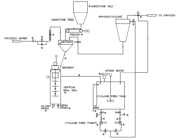
For limestone, the particle size reduction is typically done by a grinding system, which includes a feeder, a ball mill and a hydrocyclone. Sketch 1 shows a process flow diagram of a typical limestone grinding system.

Process Flow
Pebble Quicklime with the size range of ¼” x 0” is stored in the storage silo. The quicklime is withdrawn from the lime silo via the screw feeder at a predetermined rate. The lime and the water are fed simultaneously to the wetting cone where the lime and water are mixed thoroughly and flow down into the Slaking Mill. The mixture is agitated in the mill and the grit is ground. Due to the exothermic reaction of the lime and water, the temperature of the slurry rises. The RTD temperature element senses the slurry temperature and adjusts the water feed for the slaking to the wetting cone to maintain the preset value for the slaking temperature. In the winter time, when the water temperature is low, if the BTU input from the chemical reaction is not sufficient to attain the proper temperature, an auxiliary external water heater may be necessary to achieve the proper slaking temperature particularly at feed rates of less than 50% of the systems maximum capacity.
The slaked lime slurry will flow out of the Attritor Ball Mill Slaker into the Mill Product Tank. A high-energy mixer will keep the lager particles of grit in suspension in this tank.
The lime slurry is pumped from the Mill Product Tank to the Hydrocyclones for coarse separation. The Hydrocyclone underflow is returned to the Ball Mill Slaker for regrind; the overflow is discharged to the interim Slurry Staging Tank. A portion of the overflow from the Hydrocyclone is returned to the Mill Product Tank to maintain a constant level in this tank. The overflow from the Hydrocyclone is 100% smaller than 60 microns. The slurry from the Slurry Staging Tank is pumped from this tank to the bottom of an Attritor Model “C” Grinding Machine with a water-cooled jacket. When grinding the slaked lime slurry, it is important to keep the temperature of the lime slurry below 140°F to prevent agglomeration of the smaller particles. In the Attritor model “C” Grinding Machine, a portion of consumed power turns into heat due to the friction of media against media. This heat rise must be controlled so that the slurry temperature remains below 140°F. This is achieved by circulating cold water in the jacket of the mill. The pumps that feed the slurry to the Attritor model “C” Grinding Machines are equipped with a variable frequency drive. The feed rate of these pumps is controlled by the level element in the Slurry Staging Tank. The finished lime slurry exits the second mill into the Finished Product Slurry Tank. Finally, the lime slurry is transferred from this tank via transfer pumps to the Lime Slurry Storage Tank for use.
The media size in the slaking mill is 5/16” and the media size for the grinding mill is 1/8” or 3/16”, depending on the final grind required. Graph 2 shows the particle size distribution achieved by the new process.
In addition to SO2 capture in air pollution, the new process will be of great value in other industries, such as in Paper Coating for manufacturing of Precipitated Calcium Carbonate of superior quality. In this process, limestone is converted to Calcium Oxide, (CaO), by calcination. Then the Calcium Oxide (CaO) is slaked (mixed with water) to produce a slurry of Calcium Hydroxide. This slurry is converted back to Calcium Carbonate by reacting Calcium Hydroxide with CO2. In this process, Calcium Hydroxide particle size and distribution range determine the quality of the final product, Precipitated Calcium Carbonate.
An alternate to the above process is to provide a tank with temperature control as shown in Sketch 3 ahead of the slaking mill and pump the mixture of lime and water to the bottom of the slaking mill for a one pass-through. This alternate will produce even finer particles since 100% of the mixed slurry goes through the entire bed of media in the first pass through.

