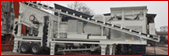


Figure 1. Laboratory Grinding Mill
Experiments were performed using a pilot mill shown in Figure 1. The mill was mounted on a milling rig as shown in Figure 2. The mill can be fitted with different liner profiles and allows a wide range of mill speeds to be used.
The mill is 0.54m-internal diameter and 0.4m internal length fitted with twelve (12) trapezoidal lifters. Figure 3 illustrates the lifter dimensions, while Table 3.1 summarises the specifications of the lifters and mill dimensions. The mill is driven by 2.5kW variable speed motor mounted in a mill rig (Moys 1984). The rig consists of three components: the supporting frame, the main shaft and the motor cage. The cage is suspended from the main axle by a set of bearings and the entire assembly is suspended from the two load cells, which are connected to a support frame. Figure 3.2 shows the assembly of the mill rig used. The motor cage is connected to a third load cell via a torque arm, which enables measurement of the force on the cage in the horizontal plane (i.e. a measure of the torque produced by the motor). The mill is designed to accommodate various modes of operation at various speeds. Using a movable diaphragm, the mill length can be changed to suit experimental need.

- 1: Front plate
- 2: Inductive proximity probe
- 3: Motor cage-bearing
- 4: Axle bearing
- 5: Axle
- 6: Supporting frame
- 7: Motor and gear box cage
- 8: 2.5 kW motor
- 9: Driving chain
- 10: Torque load beam
- 11: Torque arm
- 12: Slip ring assembly
- 13: Mirror
- 14 Infra-red LED and phototransistor

The mill is connected to the torque arm to enable measurement of forces exerted on the beam, making it possible for mill power to be obtained. An inductive proximity probe (Kiangi & Moys, 2005) designed by fellow student; inserted through the mill shell was used to obtain charge positions in reference to a 12 o’clock position that is determined using a signal produced by a light emitting diode (LED). The circuit is connected to a computer data collection system through an interface.
The mill was loaded and unloaded through a 250mm diameter opening on a removable front plate. The opening is covered during experiments to prevent material from escaping from the mill.